How it works - RTX-B-GR Series
 Fluid Process
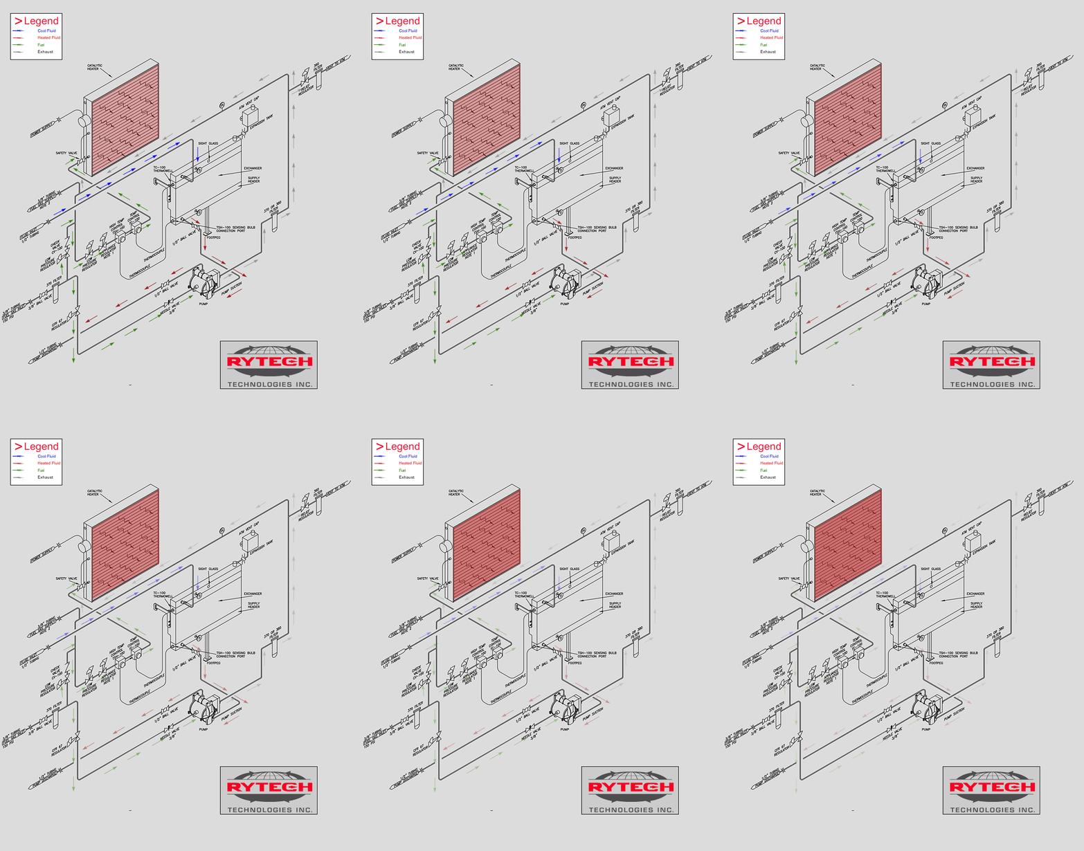
Fluid at atmospheric pressure gravity feeds down from the surge tank through the exchanger efficiently absorbing the catalytic heater’s radiant heat energy. Hot fluid is then transferred to the suction of the pump which circulates 1 - 5 gal/min through the heat-tracing loop returning cool fluid back to the surge tank where it is temperature controlled and preheated before repeating its cycle.
Header tank is equipped with temperarture utilizing the control catalytic heater’s thermostat to maintain system return fluid temperature of 10-40 C. When system reaches set temperature, the thermostat controller will adjust fuel supply to catalytic heater, utilizing only what it needs from catalytic heater to maintain system temperature.
The Radiant Tracer is also equipped with a built in high temperature shut down controller designed to completely shut off fuel supply to catalytic heater in an event the system is overheated, protecting the system and associated components.
Gas Process
RTX-B-GR Series (Gas Recovery) Models
Supply fuel gas flows through inlet filter cleaning impurities and capturing falling liquids dropping out of gas stream. Gas is then pressure regulated between 20-100 PSI through the Fisher CFR67 pressure regulator to the Inlet Flow Control Needle valve that regulates the pumps circulating rates. Pump exhausted waste gas discharges into the Vapor Recovery System where it is filtered for impurities and pressure relief regulated at 11 PSI (Max) to supply catalytic heater with fuel gas. The system bypass makeup regulator is set at 2 PSI and is utilized during initial start-up of catalytic heater or when Vapor Recovery System pressure falls below 2 PSI.
Note: Optimum gas recovery is achieved when pump exhaust pressure is maintained between 4-9 PSI fluctuating pressures controlled by adjusting the Inlet Gas Control Flow Needle Valve to pump. (See Fig. 3)
